(Part) breakups are tough
I was recently lying on the floor of my living room at 6 a.m. watching my 13-month-old son hit everything in sight with a plastic hammer when I noticed a few funny features on the underside of the toy. As soon as he grew bored, I picked up the hammer and spun it around — immediately trying to envision how and why it was manufactured the way it was. This isn’t an uncommon occurrence, and my wife has learned to no longer ask “what are you doing?” when she sees me pick up something and stare at the underside. Instead, she just smiles at me like the alien I am.
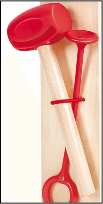
Designing products for mass production is a puzzle, and it’s one of the coolest parts of what we do. As a product design engineer, I’m tasked with creating components that must satisfy many requirements:
- They must function as intended, typically as indicated in a product requirements document. This may include surviving high or low temperatures, exposure to water, drops from large heights, caustic chemicals, and more.
- They must be manufacturable, obeying the various design rules required to ensure parts can be manufactured at scale. This requires a knowledge of various manufacturing processes, selecting the correct method based on the component, and working with partners to ensure parts can be made at scale with no issues and at a low cost.
- They need to assemble easily, generally snapping or screwing together and making it hard to do incorrectly. Bonus points are awarded when no adhesive is needed!
- They usually need to look nice. Consumer products tend to start with an industrial designer, who is responsible for creating the 3D geometry of the outside surfaces of the product and defining how a user will interact with the device.
In other mechanical engineering roles, you may not need to meet all of the above requirements. An aerospace engineer is far more focused on high reliability and weight savings than aesthetics or cost. Engineers who focus on toy design need to keep costs down as much as possible and need to ensure products meet strict testing requirements and can be assembled quickly. I love consumer electronics products because of the need to balance all the requirements, and I find this challenge so incredibly rewarding.
The process of going from a 3D model to manufacturable parts looks something like this:

Note that this is super simplistic. In reality, the industrial designer and product design engineer are working together throughout the process to ensure the product looks and works beautifully without racking up a massive budget for manufacturing. In my experience, the more collaborative this process is, the better the product turns out.
3D model of external surfaces
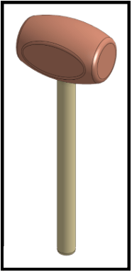
Let’s take a look at this process with the hammer toy as an example. Our industrial designer has determined that this is the ideal final shape of the hammer. It’ll feature a red plastic hammer head attached to a wooden handle.
Color, material, and finish (CMF) definition
To the uninitiated, it seems like we’re ready to roll! Let’s make thousands of these babies and move onto the next thing. In reality, we’re just getting started. Remember that “matte blue plastic” isn’t a specification.
We need to know a few key things about this product in order to make it manufacturable:
- What kind of plastic are we using? ABS, Polypropylene, HIPS? There are hundreds of different options here and our selection will impact costs, appearance, and manufacturing guidelines.
- What texture is on this hammer surface? The rougher the texture, the more draft we’ll need to apply to the mold.
- How is the handle attached? Glue? (Boooooo!) Screws? (OK!) Or is it captured another way during assembly?
- What is the exact color of the red plastic? Defining color early on may seem silly, but it helps us figure out if we can make multiple parts in the same mold and save costs.
We’ve decided to use Pantone 20-0075 TPM Red (color) Cycolac ABS plastic (material) with a Yick Sang YS1283 texture applied on all external surfaces (finish) and will press-fit the handle into the plastic housings. Excellent work — the CMF and assembly method are now defined. Let’s go manufacture it! Not quite, but we’re getting closer.
Part breakups
You’ve heard the phrase “there’s more than one way to skin a cat”? Aside from being deeply worrisome, it’s also applicable to part breakups. Remember, we need to abide by the laws of manufacturing in order to make our products. As designed, the plastic hammerhead is just too chunky to be made as a solid part using injection molding, but we need to utilize this manufacturing method to keep costs down and ensure the parts are dimensionally accurate and look great.
I’m going to get into the nerdy details here, but believe me when I say that there are many rules and terminology around injection molding that we have to factor in. Read our deep dive on molding, and feel free to skip these sections if this is TMI.
Nominal wall thickness
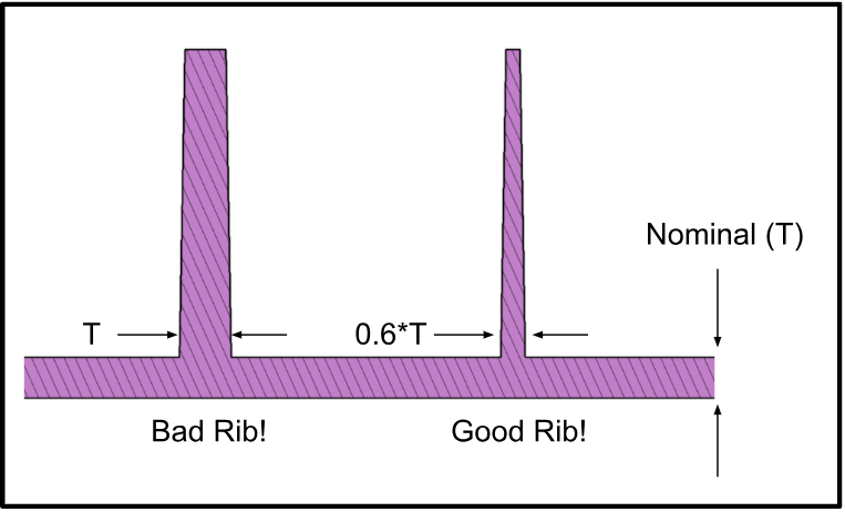
Each plastic resin has its own specifications, and we can look up our Cycolac ABS resin to see that we can make the plastic up to around 1.7 mm thick (called our nominal thickness). One fun goal of injection molding is to try and maintain this nominal thickness across the entire part. Thicker areas can cause visible deformations as the plastic cools and shrinks (called sink marks) and thinner areas can run the risk of incompletely filling during the molding process (called short shots). To be safe, we can usually go as thin as 60% of our nominal thickness without issues. Commonly, we use the terms “coring out” or “shelling” when talking about removing plastic to achieve nominal thickness.
Draft angles
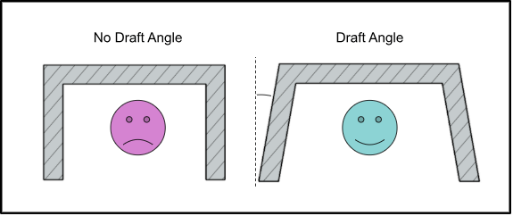
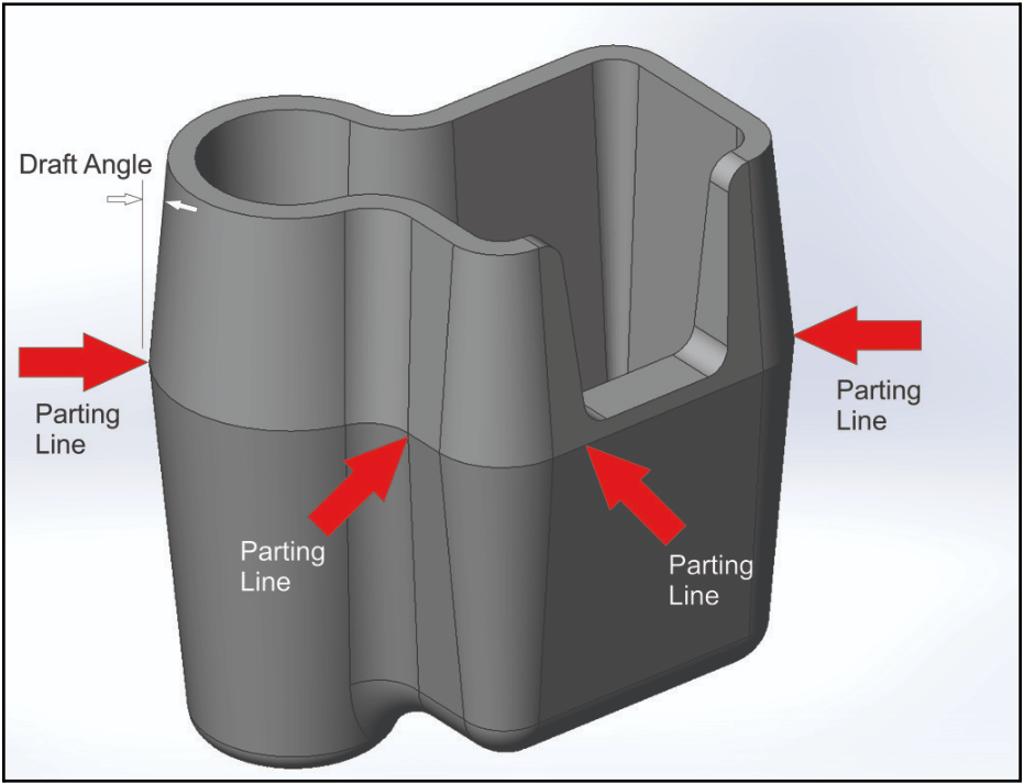
The rougher the texture on a plastic part, the steeper the draft angle required. Texture is applied to molds by physically etching into the surface, which causes friction and adhesive forces between the plastic part and the mold. A perpendicular surface has 0 degrees of draft, which is problematic.
I can look up the YS1283 texture in my design book and see that a minimum of 1.5 degrees is recommended. If we use less draft, we run the risk of parts sticking to the mold and causing damage or scratch marks on the surface. We can always use more draft though!
Undercuts, lifters, and sliders (oh my!)
Plastic parts are formed by large blocks of metals that slide together to form the mold. Then, molten plastic is injected into the gaps between the metal and cooled to form the final parts. The molds open up and the part is ejected automatically.
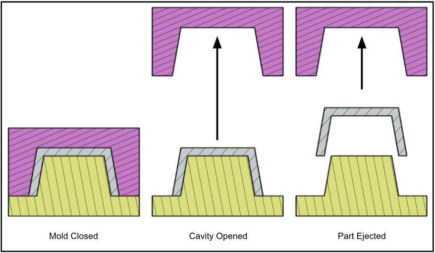
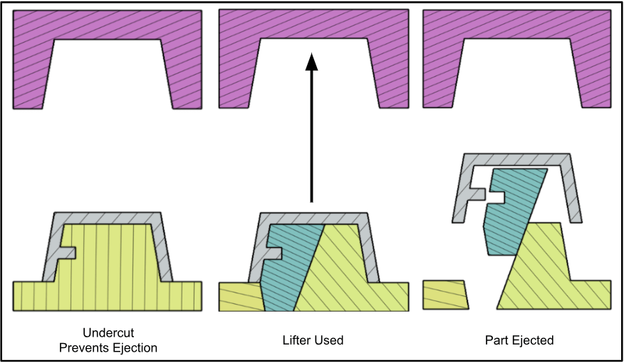
We need to ensure our parts aren’t forming undercuts in the mold, which may prevent the part from being able to eject. This is where injection molding gets really fun, as you can break the rules if you know how. Undercuts are allowed on parts as long as you add extra complexity to the mold using features known as sliders and lifters.
Lifters are added to features internal to the part. They’re a separate component that allow undercuts to be formed in plastic, but then lift up and out of the way during part ejection.
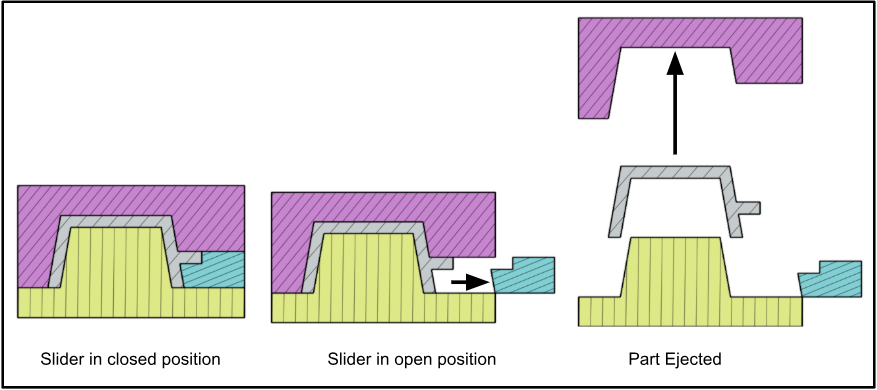
When we have an undercut on the outside of the part, we tend to use a feature called a slider. It functions similarly to a lifter, but instead slides out of the way before the part is ejected.
Parting lines
A parting line designates where the parts of the mold come together. This includes any sliders or lifters, and can appear on the plastic part as thin ridges that may protrude very slightly from the surface of the part. In order to achieve the best possible surface appearance, we try to minimize parting lines on the most visible faces. We can visualize parting lines in our CAD program easily by using a tool called draft analysis, which color-codes which sides of a part are formed with which parts of a mold. The transition between the colors indicates where parting lines will be visible.
 (image source: https://www.engineersrule.com/)
OK, now that we’re familiar with some terminology and rules, we can dive into a few ways we could break this hammer head up for manufacturing and assembly.
Option 1: Cored out
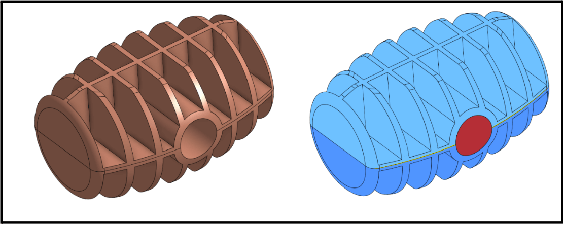
If you brought this design to a vendor without context, my guess is they would recommend a design similar to this. Here, we’ve removed the thick sections of the hammer head and have a nominal thickness of 1.7 mm everywhere. The top half of the hammer head is formed with one part of the mold, which is identical for the bottom half. A slider is used to form the hole for the wooden handle. While this certainly meets our functional requirements, my guess is that the industrial designer would disapprove of how we butchered the outer surfaces of the hammer.
Option 2: Eliminate the slider
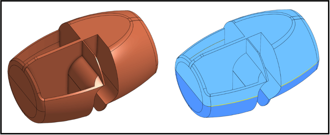
If we want to get fancier, we can remove the slider and form the feature for the handle by forming portions of the circular profile with both halves of the mold. I still think the industrial designer would be disappointed here, though, and I’d be worried that the handle may pop out over time.
Option 3: Two halves
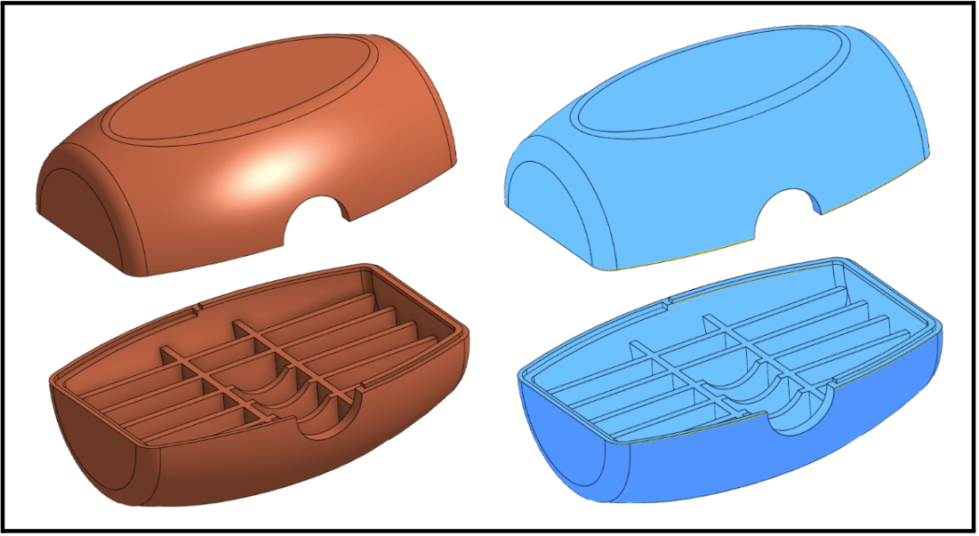
If we really want to make our industrial designer happy, we could propose using a two-piece design. The halves can be attached using screws, snaps, glue, or fancier processes like ultrasonic welding. This is a more expensive design, however, since we’re using more parts and assembly steps. Management won’t like that.
Option 4: Bottom core

If we’re really clever, we can see that not all of the surfaces of the hammer are equally important aesthetically. We can assume that the bottom of the hammer, where it connects to the handle, is less frequently seen than the top surfaces. This makes the most sense of the four proposed options, as it reduces part costs and maintains the intended industrial design as much as possible.
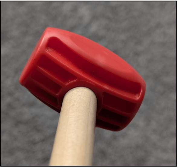 The real thing! Chew marks are not mine 🙂
What did we learn from all of this?
Well, hopefully a few things! Product design is all about defining requirements and finding the optimal solution that makes the least number of stakeholders angry. There rarely is one right solution to a problem, and it’s always worth trying various part breakup exercises to see how each option compares to the others.
informal is a freelance collective for the most talented independent professionals in hardware and hardtech. Whether you’re looking for a single contractor, a full-time employee, or an entire team of professionals to work on everything from product development to go-to-market, informal has the perfect collection of people for the job.