The informal design puck: A tool for understanding and manufacturing injection-molded parts
My favorite types of parts to design as a product design engineer are plastic injection-molded components. On the surface, they look simple to design. You might see them on products all around you and think, how hard could it be to make a good plastic part? In reality, a well-designed plastic part is a puzzle that involves deep knowledge of the rules, limitations, and opportunities of injection molding. Sometimes you might think you’ve designed a part successfully, but once it’s been mass produced, there are unexpected results. That’s why I made the informal design puck.
There are many resources available for great material samples, texture books showcasing all the possibilities, and color swatches to show exactly what the finished injection-molded product may look like. However, these are prohibitively expensive for most and can be overwhelming with the possibilities. I created the informal design puck as a resource to help clients learn about molding and show various options for texture, draft, and part sizing. Also, the informal design puck addresses a few key pitfalls I’ve noticed in other design aids that don’t accurately reflect the final results of mass-manufactured parts. If you’d like to know more about the topic, you can read my piece about the complexities of color, material, and finish.
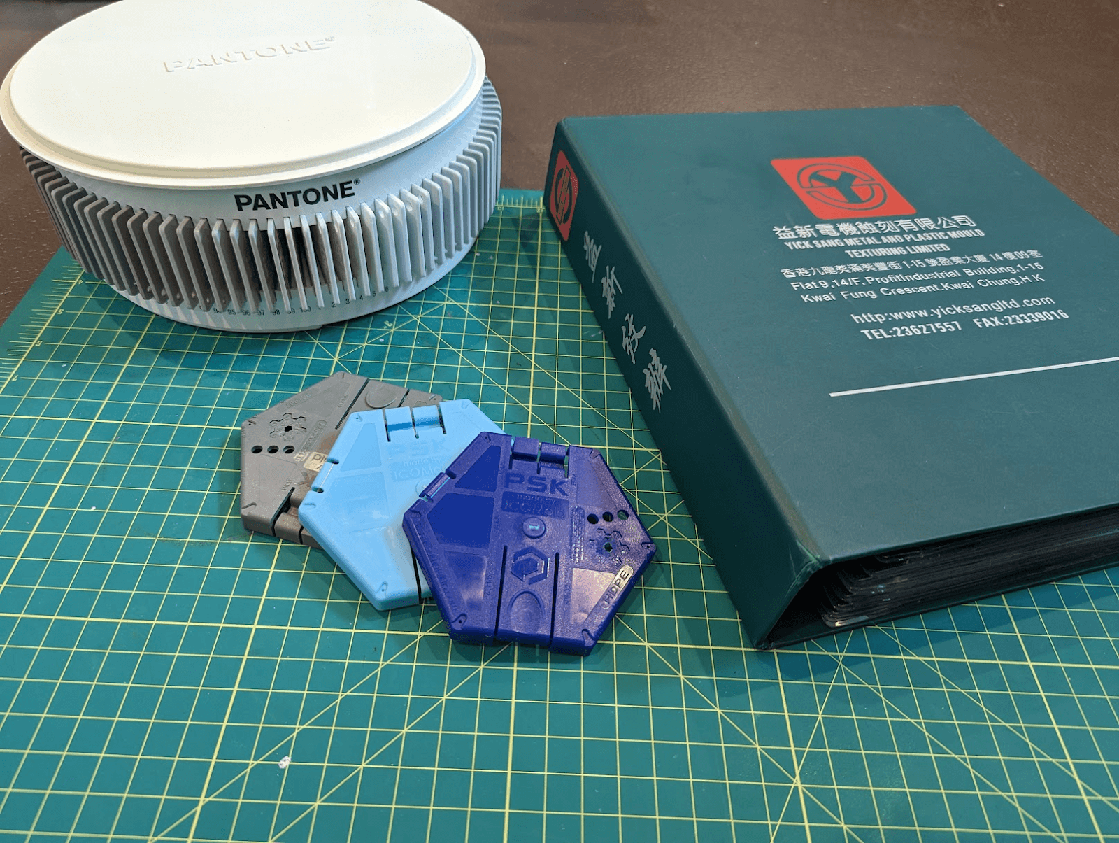
Here’s what $1,750 worth of plastic, color, and texture samples looks like.
How injection molding works
Molded plastic parts are made in a mold (surprise!) that is typically made of two or more steel blocks. These blocks form the empty shape of your part when closed together. Molten hot plastic is injected into the space between the molds, where it cools and solidifies. These molds are part of an assembly line; when it’s ready, the mold opens, ejects the solid plastic part, and closes again to repeat this process. There’s a great animated video showing the process, with a nice soundtrack to accompany it. In this article, we’ll cover how to design a part that works seamlessly with this process, including some common quirks you might not have considered. I’ve also included a few examples of how the injection molding process can leave its mark on your product, and how to get around that.
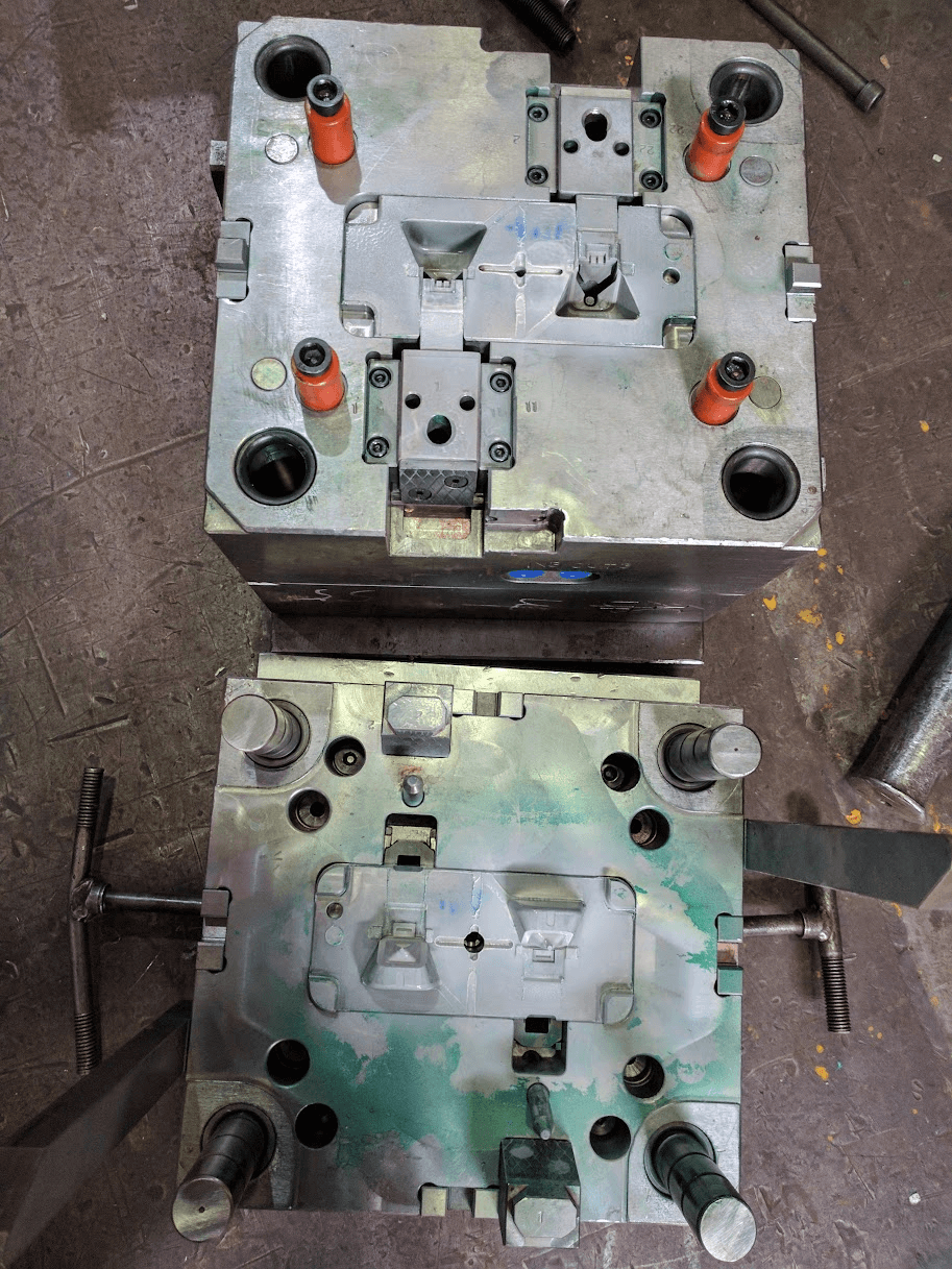
These two blocks of metal close together to form a mold.
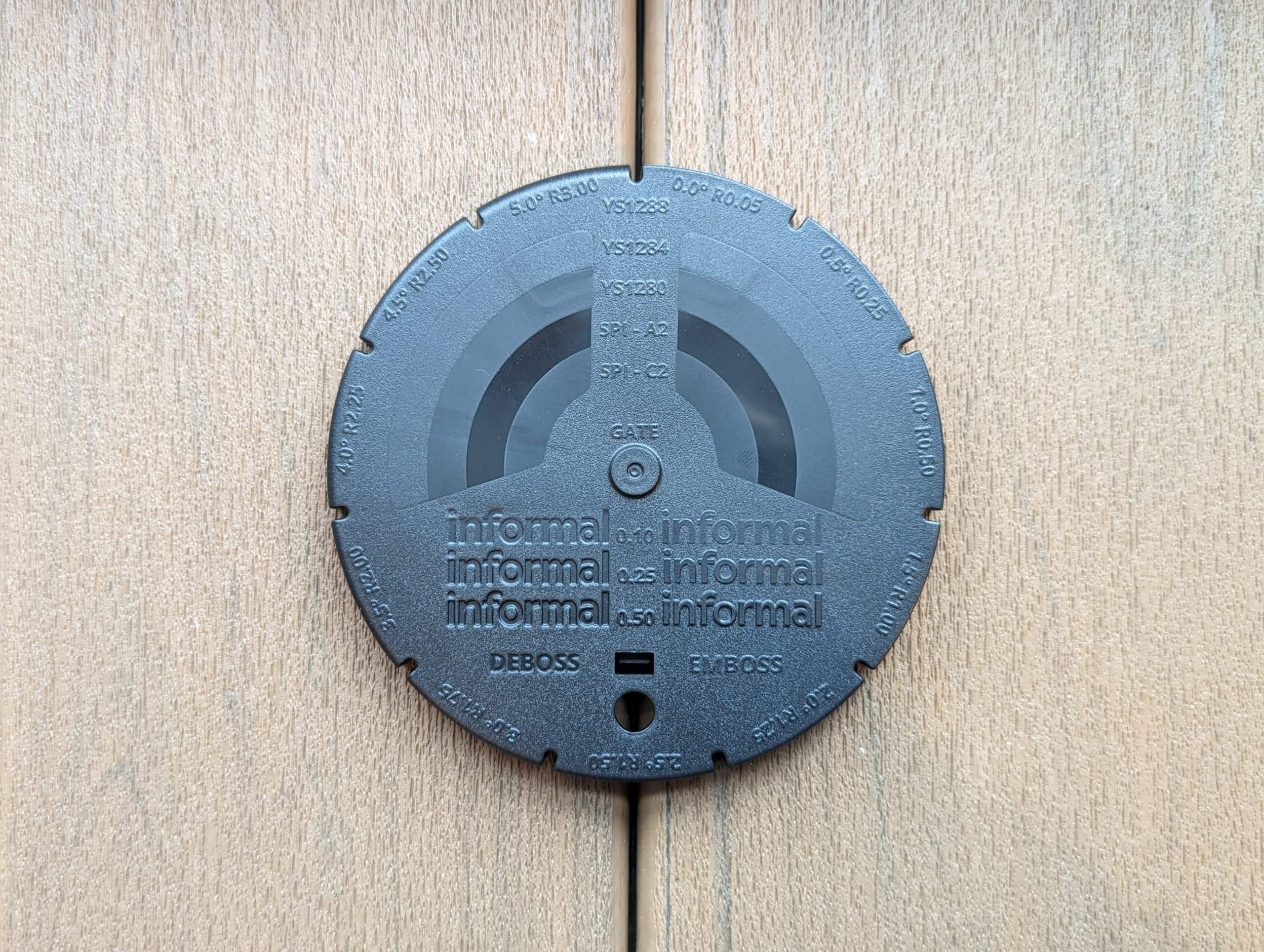
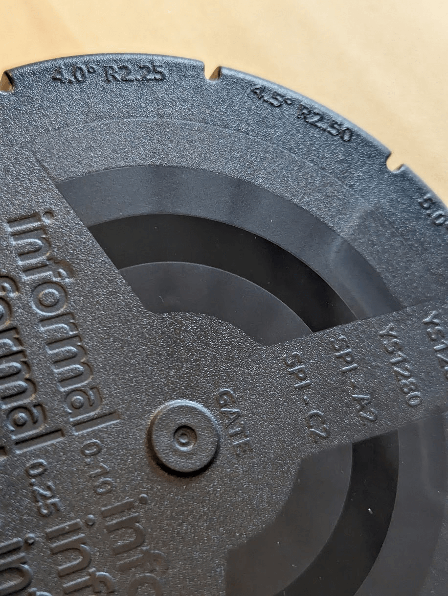
The informal design puck includes examples of how different elements will be visible on an injection-molded part. Here, you can see a variety of industry standard textures, examples of debossed and embossed logos at various heights, different draft angles, and various edge radii to give you a point of reference for your own parts. Let’s get into why each one of these features is useful, and shed some light on why injection-molded parts look the way they do.

The font of the puck shown in Onshape (left) and in reality (right). The colors indicate various molded textures.
Draft
Draft is the amount that a perpendicular surface deviates from a 90° angle. While sometimes frustrating, draft is necessary and often overlooked when manufacturing parts. Draft is needed for two important reasons: suction and friction. A part with no draft angle is very difficult to eject from a mold because it acts almost like a piston in an engine, creating suction when you try to eject it. Draft angles allow air to flow around the part during ejection, preventing damage to the part or the mold. In addition, textured parts create friction during this process and can cause parts to get stuck during ejection. The deeper the texture, the more draft is recommended. For a smooth manufacturing process, you need to understand how your part is affected by draft.
The perimeter of the puck is broken into 11 distinct “spokes.” Each spoke has a different draft angle applied to the edge. A draft angle of 0° means the surface is at a 90° angle from the other surface, and a 3° draft angle is 93° off the other surface (or 87° depending on how you want to think about it).
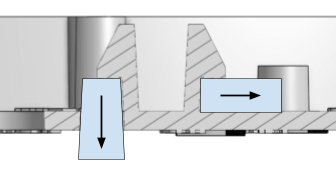
 Cross sections of the design puck showing a 0° draft angle (left) and a 3° angle (right).
Radii
Each spoke of the design puck has a different radius applied to the edge. It’s very uncommon to have a sharp edge on a cosmetic face. Sharp edges may feel too aggressive to the customer, so radii are often used to soften them. A very small radius like 0.05 mm is used to soften the edge slightly while maintaining a sharp appearance. A radius of 3 mm, by comparison, is very gentle and pillowy. I included 11 different radii on the puck and indicated the value alongside the draft using an embossed label to give you an idea of how they might turn out.
 Comparing a 0.05 mm radius with a 5 mm radius (left). Handy draft and radius information embossed on the puck (right).
Texture
The texture of your part is key! I incorporated some common textures from the YickSang texture standard, which is commonly used by vendors in China, so you can get an idea of how your product will feel. Texture is applied to the mold itself, and rougher textures require steeper draft angles. If you want to know more, or see one you like, texture books include recommended minimum draft angles for each. You can always go over the recommended draft, but going below this value is discouraged. Using a small draft angle with a rough texture can cause scrape marks to appear on the textured surface and wear down the mold more.
I included two SPI textures, the A2 high gloss and the C2 low gloss. (SPI is the Society of the Plastic Industry, in case you’re wondering.) A2 is the highest gloss level I recommend on most parts, as using higher gloss levels requires hand polishing the mold and maintaining the glossy surface, which results in expensive parts. Glossy parts typically also have a UV coating applied to reduce the tendency to scratch, and they show molding imperfections and scratches far easier than a textured surface.
Textures can vary from simple matte sandblasted finishes to simulating leopard patterning or leather to the truly bizarre. My favorite example of a crazy texture are the tiny triangles, squares, crosses and circles on the Playstation 5 system — it’s a flex and not advised for most people.

An example of a texture plaque from the YickSang book showing a recommended draft angle of 5° (left). A closeup of the PS5 texture (right).
Embossed and debossed logos
Embossing and debossing are two commonly used methods to add logos, text, and icons to molded plastic parts; they’re essentially free and a great way to minimally brand a product. Debossed designs are sunken below the surface, while embossed designs are raised up above the surface. I included various heights and depths to show how a few tenths of a millimeter can drastically change the result. It’s common to also add glossy textures to the embossed or debossed items to help make them pop.
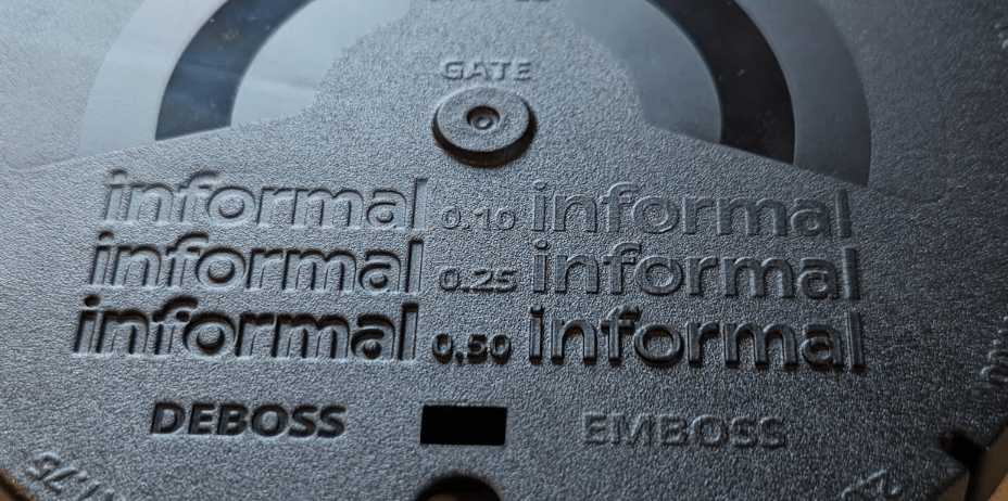 Debossed and Embossed textures with the size of each in between
The back side of the puck showcases common features found on molded parts, including snap hooks, screw bosses, ribs of various sizes, ejector pins, and wall thickness transitions. Cosmetic imperfections like sink marks and knit lines are also present on the puck as a way to understand the impacts of part design on appearance.
 The back of the puck shown in Onshape (left) and in reality (right).
Ribs
Ribs are protruding features that are used to add stiffness, aid in plastic flow, or to retain or align additional components within an assembly. Most molded parts have ribs for various reasons. As the plastic cools, it contracts, and if a rib is too thick, it can deform the other side of the plastic part. This causes something called “sink marks,” which look like small divots or deformation on the flipside of the rib.
In order to mitigate sink marks, design the rib to be some percentage of the plastic thickness. I’ve included a few ribs of various thicknesses to show the sink marks they can cause on the front side of the part. I also designed the ribs to pass over various textured areas on the part, so you can see how the texture masks the sink mark on the larger ribs. Understanding the potential issues with ribs can help you steer clear of them.
 Sink marks from the thicker ribs showing through on the textured surfaces. Note how the matte textures hide the sink marks better.
Ejector pins
Every part has ejector pins, which are used to remove the plastic part from the mold. They’re typically small rods or bars of metal that press forward when the mold is open and physically eject the plastic part out of the mold. The ejected plastic part is usually removed by a robotic arm or an operator.
The placement of ejector pins is often done by the molding vendor, based on their knowledge of how materials shrink, where features are located on the part, and through running simulation. Ejector pins tend to be on the side of the part that is more likely to stick to the mold half when opened, typically the side with more surface area. It’s important to work with vendors to review their tooling drawings to verify that the placement of ejector pins won’t impact the appearance or the functionality of the part, or you might be left with a surprise. I’ve included an example of an ejection pin print on the puck, and now you’ll recognize them everywhere!
Ejector features called out by the vendor for the Lodge Solar Speaker top housing (left). Ejector pin on the puck (right).
Snap hooks
A common fastening method is the handy old snap hook. These features take advantage of the elasticity of most plastics, allowing a molded-in hook shape to deform during assembly and snap back into position, locking itself in place. Snap hooks are typically found on the battery doors of remote controls and smoke detectors, but are also used internally to help hold parts together without screw features. They’re a simple way to hide all assembly features at the expense of making it much harder to disassemble. Proper snap hook geometry is key to success, and you can read entire books on the topic if you have the interest and time.
I used two key molding techniques to form the snap hooks on our puck: shutoffs and lifters. Both of these techniques address a key issue with any feature that creates an “undercut” in a molded part. This video does a fantastic job of explaining what an undercut is. If you can poke a hole in the opposite side of your part, you can extend the metal from the mold through the part to create your snap hook. This is called a “shutoff,” as metal shuts off the flow of plastic to the surrounding areas.
 Snap hooks formed using a shutoff feature (left) and a lifter (right).
Thin sections
The rule of thumb with molding plastic parts is to keep the thickness of the part as consistent as possible. This helps to ensure molten plastic can flow to all corners of your part successfully. There are exceptions to this rule — namely when trying to reduce sink marks from ribs, screw bosses, snap hooks, and other features you may add.
If you do need to reduce the thickness of an area in a plastic part, do so as gradually as possible. One of the largest drivers in cosmetic issues on plastic parts is caused by these rapid changes in thickness, causing visible marks on the opposite side of the part, known as “read through” marks.
I added two stepped features to the back side of the puck, where I dropped the thickness to various amounts of the wall thickness to see the impact on the cosmetic side. The stepped features on the right side are drastic changes, while the left side is less drastic. Honestly, both look pretty bad, but the transitions are harder to see where the change is more gradual.
 Smooth transitions (left) compared to abrupt (center) in the CAD model. The “read through” on the front side of the puck (right).
Knit lines
Knit lines are a side effect of the molding process, and they occur due to the plastic flowing around features and solidifying. In the design puck, I have two openings near each other, which requires plastic to flow around metal parts and join back together. When the plastic flows meet back, there’s a small line that forms. These lines can be fairly visible depending on the size of the surrounding features, the color and texture of the part, and the material used. You can mitigate this by adjusting the number and placement of gates on your plastic part, but it’s nearly impossible to remove them entirely. Work with your vendor to ensure the gate locations work with your part geometry, and use mold flow simulation tools to see where knit lines may occur.
 Knit lines appear as brighter lines between openings on a part (right). Mold flow showing where molten plastic will meet and can cause knit lines.
Other things to know
Parting lines are the locations on a part where the components of the mold meet. Sometimes, excess plastic may form here, causing an issue known as flash. It’s also common to have sharp edges at the parting line, so it’s important to try and keep these edges away from surfaces that customers may interact with.
Every injection-molded part has a gate, where the molten plastic is injected into the part. There are many types of gates, and the use of each one depends on the part geometry, cosmetic requirements, size, material, and more. I chose a visible gate in the center as a design aid, but would typically work with the vendor to hide this as much as possible. Anyone who’s built a plastic model kit will be familiar with gates and how critical it is to remove them from a plastic part to reduce the impact on the appearance.
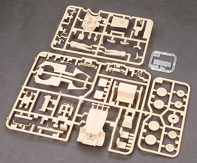 A plastic model kit showing gates for each plastic part. (Source: Tamiya)
 The parting line of the design puck shown in yellow (left). Flash from a poorly mating mold (right; source).
When two molded parts are attached together, there’s a chance they may not sit perfectly flush with one another. A reveal groove is a common technique used by designers and engineers to add a visible and controlled groove between the parts to help hide any imperfections. Another common molding technique is to use a slider to allow for 0° draft on the outside of parts, add holes perpendicular to the molding direction, and for fastening features. Since sliders add more parts to the mold, they tend to increase the cost and add additional parting lines that may be visible.

A beautiful reveal groove made by yours truly on the Neurosity Crown (left). A small step in the plastic housing from the slider on the Aloe Care Hub made by yours truly (right).
Screws are everywhere in products, so it’s important to know how to integrate them without adding too much cost or confusion, whether you’re securing a circuit board or adding a pivot point for a mechanism. Each fastener application is unique, but I recommend using thread-forming screws where possible to streamline assembly and reduce costs. My favorite is the M3 x 6 mm pentalobular screw with a Torx T10 head — a classic! Alternatively, you can add metal threaded inserts into plastic parts where additional strength or durability is required. The datasheet for the screw or insert will include the proper geometry to use to ensure a reliable connection. One trick I’ve picked up over the years is to add a small recess around the screw boss to reduce the chances of causing a sink mark on the opposite side. In addition, a small tapered lead helps to locate the screw during assembly.
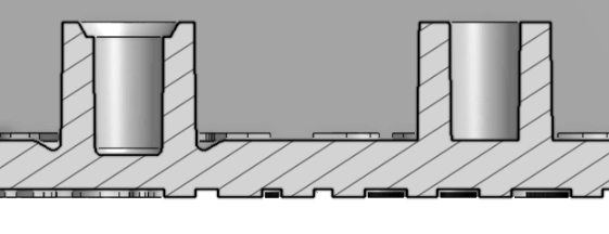 Good (left) and bad (right) screw boss design. Note the tapered lead in, recessed perimeter, and deeper hole on the good design.
If you’re looking to design an injection-molded part, it’s good to really understand what that process means so you’re not surprised when your product comes back with ejection pin markings, sink marks, poor texture, or fitment issues. We’ve got experts to help you navigate this sea of constraints and get ahead of your manufacturing problems.
Looking to get a sample of this sweet design puck? Fill out this form to request one.
Looking for plastics experts? Reach out to us and we’ll be in touch!
informal is a freelance collective for the most talented independent professionals in hardware and hardtech. Whether you’re looking for a single contractor, a full-time employee, or an entire team of professionals to work on everything from product development to go-to-market, informal has the perfect collection of people for the job.